VIET WATER JSC provides professional wastewater treatment system design services focused on emission...
Renovation of Livestock Wastewater Treatment Systems
Renovation of Livestock Wastewater Treatment Systems – VIET WATER Technology Solutions
Renovating a livestock wastewater treatment system is an essential solution when an existing facility can no longer handle the required wastewater flow, meet effluent quality requirements, or maintain acceptable operating costs. Instead of constructing an entirely new system, livestock farm owners can assess each treatment stage to determine which components need repair, upgrading, or additional treatment technologies.
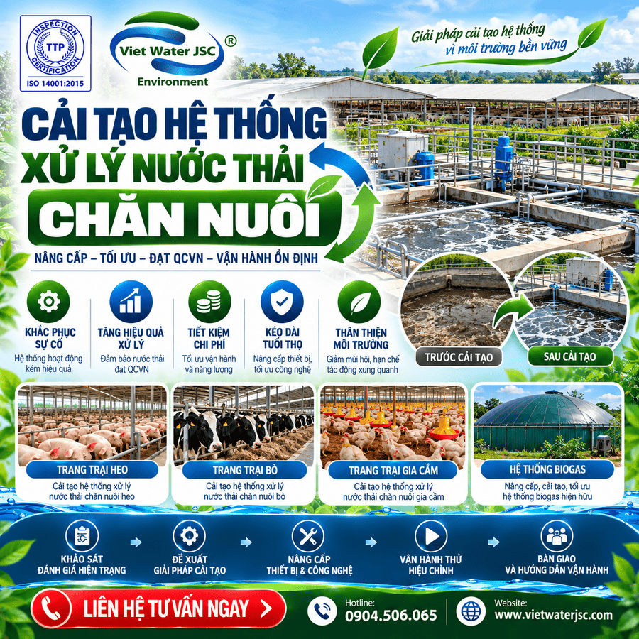
VIET WATER JOINT STOCK COMPANY (VIET WATER JSC) provides consulting, design, fabrication, installation, renovation, and operational optimization services for livestock wastewater treatment systems. Depending on the existing conditions, renovation may involve upgrading anaerobic biogas tanks, equalization and settling ponds, nitrogen treatment towers, physicochemical treatment units, Anoxic tanks, Aerotank tanks, biological ponds, MBR filtration and absorption systems, disinfection tanks, and auxiliary facilities.
The key to successful renovation is identifying the actual technical limitations of the existing system. If the problem originates from inadequate solids separation, upgrading the biological treatment tank alone may not solve it. If the system lacks an effective nitrogen removal stage, the entire treatment sequence must be evaluated rather than simply increasing the capacity of the aeration blower.
VIET WATER’s Livestock Wastewater Treatment System Renovation Process
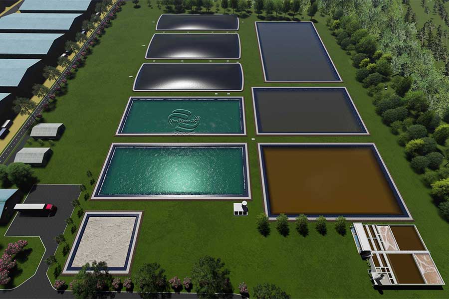
The technology flow diagram provided by VIET WATER organizes the treatment process into a main wastewater line, with auxiliary lines for gas, chemicals, sludge, and recirculation.
1. Anaerobic Biogas Tank
Receives wastewater from the livestock farm and uses anaerobic treatment to reduce part of the organic pollutant load. Biogas is collected through an auxiliary system and may be used for power generation or other suitable purposes, depending on actual operating conditions.
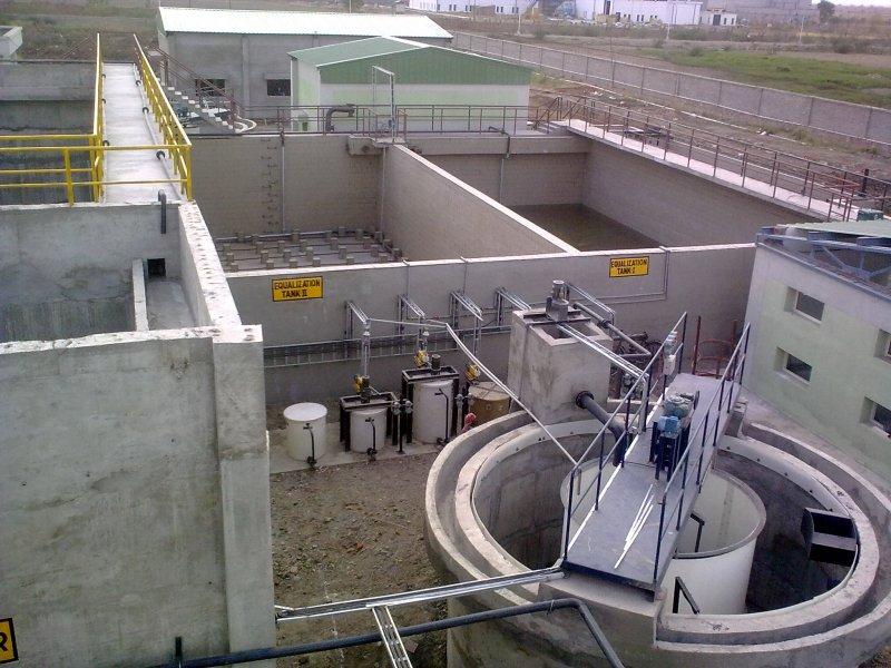
2. Equalization and Settling Pond
Receives wastewater from the biogas tank, helps balance flow rates, and stabilizes the wastewater before it enters the nitrogen treatment tower. The diagram also shows chemical dosing and pumping equipment.
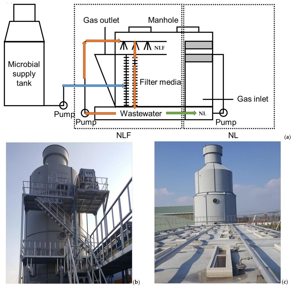
3. Nitrogen Treatment Tower
A dedicated nitrogen treatment stage equipped with air supply and chemical dosing lines. During renovation, the air supply, chemical dosing conditions, and actual nitrogen removal performance should be inspected.
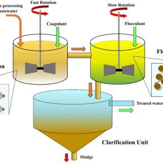
4. Physicochemical Treatment Unit and Chemical Clarifier
Wastewater flows from the nitrogen treatment tower into the physicochemical treatment unit, where chemicals are added as required. Suspended solids are then separated in the chemical clarifier. Chemical sludge is conveyed to the sludge storage system according to the process diagram.
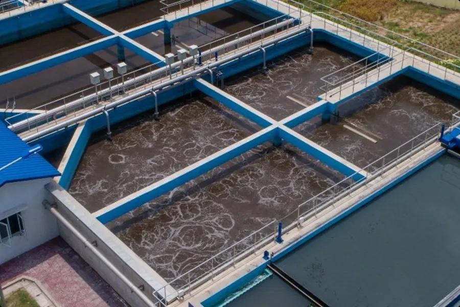
5. Anoxic Tank and Aerotank
These biological treatment stages further remove pollutants remaining in the wastewater. The diagram shows air supply to the Aerotank and recirculation lines connecting the secondary sludge clarifier, Aerotank, and Anoxic tank.
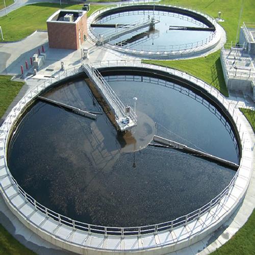
6. Secondary Sludge Clarifier and Biological Pond
The secondary clarifier separates sludge from the treated water after Aerotank treatment. Water then flows into the biological pond, which has a Nano-aeration line shown in the diagram. Sludge is conveyed to the sludge storage pond, with recirculation lines arranged according to the system design.
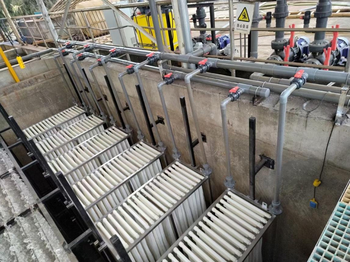
7. MBR Filtration and Absorption
This is the advanced treatment stage before disinfection in the diagram. A membrane regeneration solution line is provided. During renovation, the membrane condition, transmembrane pressure, and cleaning procedures should be checked.
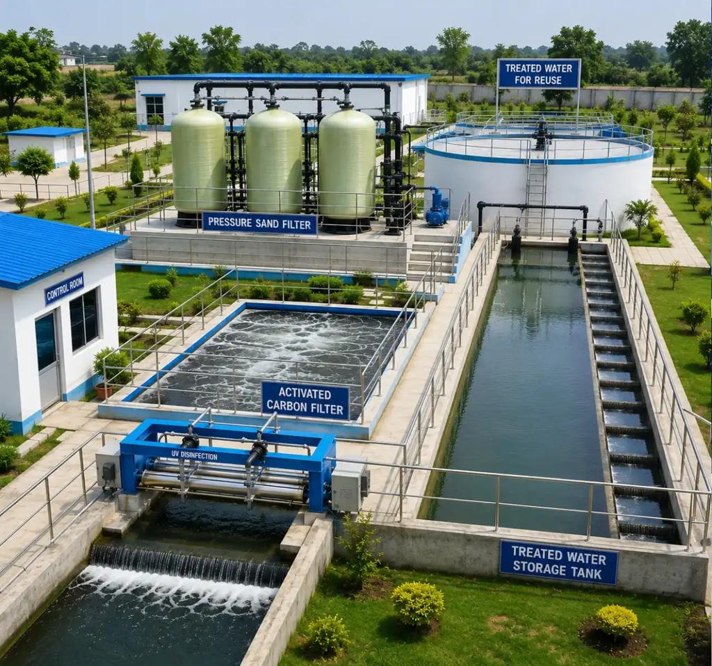
8. Disinfection Tank and Reuse Water Storage Pond
Water from the MBR stage enters a disinfection tank with chlorine dosing before being transferred to the storage pond for potential reuse, subject to the actual water quality and intended application.
Technical Assessment of Each Treatment Stage
Renovation of the Anaerobic Biogas Tank
The anaerobic biogas tank is the first treatment stage receiving wastewater from the livestock farm. For facilities that have been operating for many years, the structure, sludge accumulation, gas pipelines, gas collection system, and wastewater inlet and outlet should be inspected.
Potential renovation work includes:
-
Repairing leaks and structural damage.
-
Inspecting biogas pipelines and gas collection equipment.
-
Checking sludge and sediment accumulation.
-
Clearing blocked wastewater inlet and outlet pipes.
-
Evaluating treatment performance before wastewater enters the equalization pond.
According to the VIET WATER process diagram, collected biogas may be used to operate a generator or support suitable production activities. Gas utilization must be accompanied by appropriate collection, safety controls, and operating procedures.
Upgrading the Equalization and Settling Pond
After anaerobic treatment, wastewater flows into the equalization and settling pond before being pumped to the nitrogen treatment tower.
Renovation should assess the effective tank volume, actual inflow, sedimentation conditions, pump performance, and wastewater supply rate to downstream treatment stages.
If the pond is undersized or the pumping flow is unstable, fluctuating hydraulic and pollutant loads may reduce the performance of nitrogen removal and biological treatment.
Potential improvements include structural repairs, pump and pipeline upgrades, sediment removal, and operating adjustments based on actual wastewater flow.
Upgrading the Nitrogen Treatment Tower
The nitrogen treatment tower is an important component of the VIET WATER process diagram. It is positioned after the equalization pond and includes air supply and chemical dosing lines.
If nitrogen removal performance is inadequate, the following should be checked:
-
Air supply equipment.
-
Air distribution performance.
-
Wastewater flow through the tower.
-
Chemical dosing conditions.
-
Nitrogen concentrations before and after treatment.
-
Scaling, fouling, or equipment blockages.
Adjustments should be based on wastewater characteristics and laboratory results. Increasing chemical dosage or airflow without identifying the underlying problem may increase operating costs without improving treatment performance.
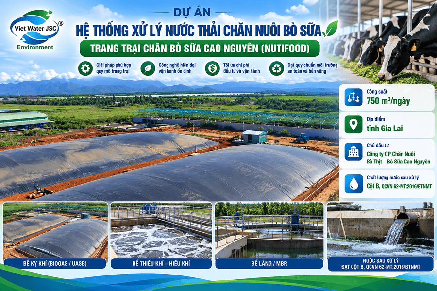
Renovating the Physicochemical Treatment Unit and Chemical Clarifier
After nitrogen treatment, wastewater passes through the physicochemical treatment unit and chemical clarifier.
These stages should be inspected when the effluent contains excessive suspended solids, clarification performance is poor, or chemical consumption has increased.
Potential renovation items include:
-
Inspecting chemical dosing pumps.
-
Checking chemical dosing pipelines.
-
Adjusting dosing points and operating conditions.
-
Inspecting mixing equipment.
-
Evaluating floc formation and settling performance.
-
Checking sludge collection equipment.
-
Removing accumulated sludge from tanks.
According to the diagram, chemical sludge is transferred to the sludge storage system. Renovation must therefore consider sludge collection and handling, not only water quality.
Renovating the Anoxic and Aerotank Systems
After chemical clarification, wastewater enters the Anoxic tank and Aerotank.
These biological treatment stages are important for removing the remaining pollutants. The diagram shows an air supply line to the Aerotank and recirculation lines connecting the secondary sludge clarifier, Aerotank, and Anoxic tank.
During renovation, VIET WATER should assess:
-
Air supply and distribution.
-
Biological sludge concentration.
-
Sludge recirculation.
-
Internal recirculation between tanks.
-
Mixing conditions in the Anoxic tank.
-
Organic loading.
-
Foam, sludge flotation, or poor settling.
If oxygen supply is inadequate, the blower and air distribution system should be assessed. If nitrogen removal is insufficient, the Anoxic zone, aerobic zone, recirculation ratio, and biological conditions must be evaluated together.
Renovating the Secondary Sludge Clarifier
Water from the Aerotank flows into the secondary sludge clarifier, where sludge is separated before the water enters the biological pond.
If clarification is unstable, solids may carry over into downstream stages, increasing the load on the biological pond and MBR system.
Key inspection items include:
-
Hydraulic and solids loading rates.
-
Sludge settling characteristics.
-
Sludge collection mechanisms.
-
Sludge recirculation lines.
-
Waste sludge discharge lines.
-
Sludge flotation or washout.
Corrective work at this stage can reduce solids carryover and improve the stability of downstream treatment.
Renovating the Biological Pond and Nano-Aeration System
According to the VIET WATER process diagram, water from the secondary sludge clarifier flows into the biological pond. A Nano-aeration line is shown supplying air to this pond.
Renovation should evaluate pond conditions, inflow capacity, sludge accumulation, odor generation, and the condition of the aeration equipment.
Potential improvements include:
-
Removing accumulated sediment when necessary.
-
Inspecting air distribution pipelines and equipment.
-
Evaluating air distribution performance.
-
Reviewing hydraulic retention time.
-
Addressing stagnant areas or odor issues.
-
Checking water quality before it enters the MBR stage.
Additional aeration equipment or changes to the air supply should be based on the pond's treatment objectives and operating conditions. Increasing aeration does not automatically improve performance in every situation.
Upgrading the MBR Filtration and Absorption System
The MBR filtration and absorption stage is positioned after the biological pond and before disinfection in the VIET WATER process diagram.
This stage should be assessed when effluent quality is unstable or the membrane system experiences operational problems.
Inspection items include:
-
Membrane condition.
-
Transmembrane pressure and filtration flow.
-
Membrane fouling or clogging.
-
Pumps and pipelines.
-
Membrane aeration, where applicable.
-
Cleaning and regeneration procedures.
-
Water quality entering and leaving the membrane stage.
The diagram includes a regeneration solution line to the MBR filtration and absorption stage. The solution type, concentration, contact time, and cleaning procedure must follow the technical requirements of the actual membrane and equipment.
Renovating the Disinfection Tank and Reuse Water Storage Pond
After MBR treatment, water enters a disinfection tank with a chlorine dosing line before flowing to the reuse water storage pond.
Renovation should inspect the dosing pump, chemical injection equipment, mixing conditions, contact time, and storage pond condition.
Water should only be reused when its quality meets the requirements of the intended application. If higher-quality water is needed, additional filtration may be assessed based on technical requirements and economic feasibility.
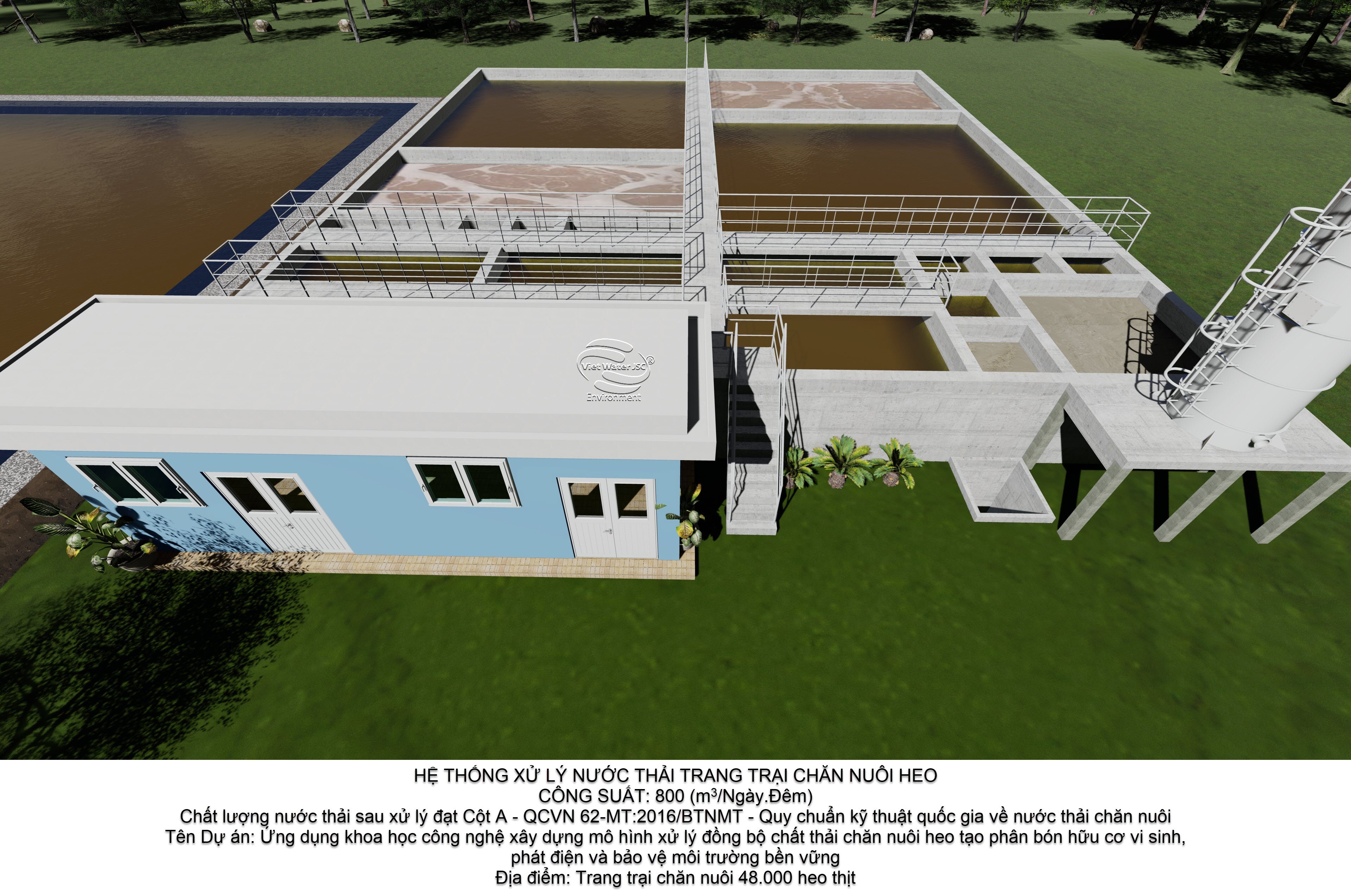
Renovating Sludge Collection and Treatment Systems
The VIET WATER process diagram shows sludge lines from the chemical clarifier, secondary sludge clarifier, and related facilities leading to the sludge storage area. Sludge is transferred to the storage pond for management according to the project plan.
When renovating the sludge system, the following should be checked:
-
Sludge pipelines.
-
Sludge pumps and pumping capacity.
-
Sludge accumulation inside tanks.
-
Effective capacity of the sludge storage pond.
-
Dewatering or sludge treatment equipment, where installed.
-
The sludge management and disposal plan.
Chemical sludge and biological sludge must be managed according to their characteristics and applicable regulations. Not all sludge can automatically be used as fertilizer or discharged into the environment.
Benefits of Renovating the System According to VIET WATER’s Process Diagram
A coordinated renovation program can provide several benefits:
Utilizing existing facilities: Retaining tanks, ponds, and equipment that remain technically suitable helps avoid unnecessary investment.
Improving treatment performance: Identifying and correcting underperforming stages can improve effluent quality.
Optimizing equipment: Pumps, blowers, mixers, and chemical dosing systems can be adjusted or replaced where necessary.
Improving nitrogen and organic pollutant removal: Evaluating the nitrogen treatment tower, physicochemical treatment, Anoxic tank, and Aerotank as an integrated process.
Improving advanced filtration: Inspecting the MBR filtration and absorption system and disinfection tank can improve effluent stability.
Improving sludge management: Coordinating chemical sludge, biological sludge, and storage systems reduces operational problems.
Supporting water reuse: Monitoring water quality in the storage pond helps determine whether reuse is appropriate.
Actual results depend on the facility's initial condition, the scope of renovation, influent wastewater quality, and operating practices after the upgrade.
Cost of Renovating Livestock Wastewater Treatment Systems
Renovation costs cannot be accurately determined from nominal treatment capacity alone. A site survey is needed to assess tank conditions, equipment, pipelines, and wastewater quality.
|
Renovation item |
Main cost factors |
|---|---|
|
Biogas tank |
Structure, gas pipelines, sludge accumulation, and treatment capacity |
|
Equalization pond |
Effective volume, pumps, mixing, and pipelines |
|
Nitrogen treatment tower |
Air supply, chemical dosing, and nitrogen removal performance |
|
Physicochemical treatment |
Dosing pumps, mixing, clarification, and sludge collection |
|
Anoxic and Aerotank |
Tank volume, aeration, recirculation, and biological treatment |
|
Secondary sludge clarifier |
Sludge collection, sludge pumps, and settling performance |
|
Biological pond |
Sediment, pond condition, and Nano-aeration system |
|
MBR filtration and absorption |
Membranes, pumps, auxiliary equipment, and cleaning procedures |
|
Disinfection |
Chlorine dosing, mixing equipment, and contact time |
|
Sludge system |
Pumps, pipelines, storage, and sludge treatment equipment |
To prepare a practical proposal, the owner should provide the existing process diagram, design capacity, wastewater flow, laboratory results, and photographs of tanks and equipment.
VIET WATER’s Renovation Implementation Process
VIET WATER can carry out renovation projects through the following steps:
-
Initial information gathering: Collect information about livestock operations, design capacity, and current problems.
-
Site inspection: Inspect tanks, ponds, pipelines, pumps, blowers, and control systems.
-
Wastewater assessment: Identify the parameters that need to be controlled and the stages limiting treatment performance.
-
Root-cause analysis: Determine whether the problem is caused by equipment failure, overloading, operating conditions, or an unsuitable process configuration.
-
Renovation proposal: Identify which components should be retained, repaired, upgraded, or replaced.
-
Cost estimate and construction plan: Define the scope, budget, schedule, and operating coordination requirements.
-
Renovation works: Implement the agreed improvements.
-
Commissioning and optimization: Adjust equipment, recirculation, aeration, and operating conditions.
-
Handover: Provide operating and maintenance guidance and instructions for monitoring effluent quality.
The construction schedule should account for ongoing farm operations and control risks when individual treatment stages need to be temporarily shut down.
VIET WATER – Livestock Wastewater Treatment System Renovation Provider
VIET WATER JOINT STOCK COMPANY provides renovation solutions based on the existing condition and objectives of each project. The scope may include upgrading biogas tanks, equalization ponds, nitrogen treatment towers, physicochemical treatment units, Anoxic tanks, Aerotank tanks, biological ponds, MBR filtration and absorption systems, disinfection facilities, and sludge collection systems in accordance with the company's process diagram.
VIET WATER focuses on identifying the actual technical causes of system problems, retaining suitable existing facilities, and recommending upgrades based on treatment performance, investment costs, and long-term operating requirements.
Contact VIET WATER for Livestock Wastewater Treatment System Renovation
VIET WATER JOINT STOCK COMPANY
-
Address: 345 Pham Van Bach Street, Tan Binh Ward, Ho Chi Minh City, Vietnam
-
Representative Office: Ban Thach 1, Sao Vang Commune, Thanh Hoa Province, Vietnam
-
Fabrication Workshop: Thanh Xuan 52 Street, Thanh Xuan Ward, Ho Chi Minh City, Vietnam
-
Phone: +84 28 6272 4888 – +84 904 506 065
-
Email: Info@vietwaterjsc.com
-
Website: www.vietwaterjsc.com